








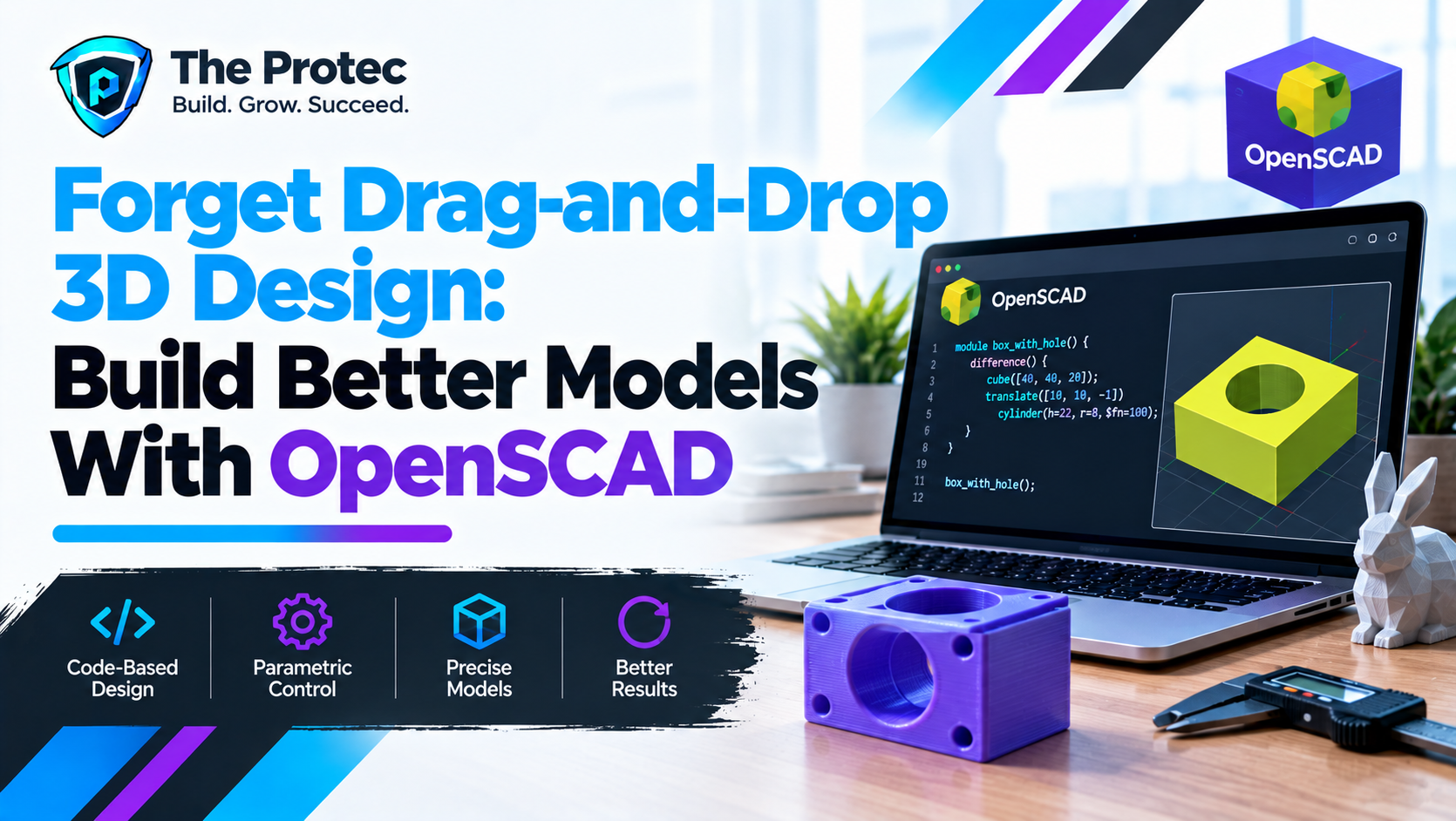
Most 3D design applications ask you to click, drag, rotate, and resize objects on a canvas. OpenSCAD takes a radically different approach: you describe the model in code. Change a number, render the script again, and the geometry updates predictably.
That code-first workflow makes OpenSCAD especially compelling for programmers, engineers, makers, and 3D-printing enthusiasts. Instead of manually adjusting dozens of faces, you can define a bracket’s width, wall thickness, hole diameter, and other dimensions as variables. The same script can then produce an entire family of parts.
As of October 2026, this style of programmatic CAD design is increasingly relevant to customizable products, distributed manufacturing, open hardware, and version-controlled engineering projects. OpenSCAD is not intended to replace every visual modeling package, but it remains one of the most approachable ways to explore precise 3D modeling with code.
What Is OpenSCAD 3D Modeling Software?
OpenSCAD is free, open-source CAD software for creating solid 3D models with a textual scripting language. It is available from the official OpenSCAD website and runs on Windows, macOS, and Linux.
Unlike interactive CAD tools, OpenSCAD does not focus on selecting faces or pushing control points with a mouse. Its editor accepts statements that create and transform geometry. A preview window shows the result, while the source file remains the authoritative description of the design.
The OpenSCAD programming language is more accurately described as a declarative modeling language than a general-purpose language. You specify what the geometry should be, and OpenSCAD evaluates that description. Its support for variables, mathematical expressions, loops, functions, and modules makes it feel familiar to developers without requiring a large software framework.
This combination has earned OpenSCAD a place among the best CAD software for programmers. Scripts are readable, easy to duplicate, suitable for Git-based version control, and capable of generating customizable 3D printable models from a small set of parameters.
OpenSCAD Tutorial: Core Concepts for Beginners
Start With Primitive Shapes
Most OpenSCAD examples begin with primitives such as cubes, spheres, cylinders, and polyhedra. Dimensions are passed as arguments, and transformations position the resulting objects in three-dimensional space.
cube([40, 20, 5]);
translate([20, 10, 5])
cylinder(h = 10, d = 8, $fn = 48);
This script creates a rectangular base and places a cylinder on top. The translate() operation moves the cylinder along the X, Y, and Z axes. Other common transformations include rotate(), scale(), mirror(), and resize(). Indentation is optional to the interpreter but essential for readable models.
Combine Geometry With Boolean Operations
Boolean operations are central to code-based 3D modeling. union() combines solids, difference() subtracts later objects from the first object, and intersection() keeps only the volume shared by all included shapes.
difference() {
    cube([30, 30, 8]);
    translate([15, 15, -1])
        cylinder(h = 10, d = 6, $fn = 48);
}
The result is a plate with a circular hole. Extending the subtracting cylinder beyond both surfaces helps prevent ambiguous, coincident faces that can cause rendering artifacts.
Control Dimensions With Variables and Expressions
OpenSCAD variables and modules turn fixed geometry into parametric geometry. Instead of repeating dimensions throughout a file, assign meaningful names and derive related values mathematically.
outer_diameter = 20;
wall = 2;
height = 8;
inner_diameter = outer_diameter - (2 * wall);
Changing outer_diameter now updates the derived opening automatically. This is the foundation of parametric design for 3D printing: dimensions express the design’s intent rather than isolated edits.
Repeat Features With Loops
OpenSCAD loops and functions are useful when a model contains repeated vents, mounting holes, teeth, or grid cells. A for loop can position identical geometry using calculated coordinates.
for (x = [10 : 10 : 50]) {
    translate([x, 10, 0])
        cylinder(h = 5, d = 3, $fn = 32);
}
This produces five evenly spaced cylinders. Place the loop inside a difference() operation and the same cylinders become holes. Because the spacing rule is encoded, adding another feature does not require manually aligning it.
Reuse Geometry With Functions and Modules
Functions calculate and return values, while modules define reusable geometry or operations. A module can accept parameters, hide implementation details, and be called repeatedly.
module spacer(outer_d, inner_d, length) {
    difference() {
        cylinder(h = length, d = outer_d, $fn = 64);
        translate([0, 0, -0.1])
            cylinder(h = length + 0.2, d = inner_d, $fn = 64);
    }
}

spacer(14, 6, 10);
The module can generate spacers for different fasteners without copying the full model. This modular approach is one reason OpenSCAD works well as CAD software for developers.
Building a Customizable 3D-Printable Bracket
A simple L-shaped mounting bracket demonstrates how primitives, Boolean subtraction, variables, loops, and modules work together.
width = 60;
depth = 25;
height = 40;
wall = 4;
hole_diameter = 5;

module mounting_holes() {
    for (x = [10, width - 10]) {
        translate([x, -1, 12])
            rotate([-90, 0, 0])
                cylinder(h = wall + 2, d = hole_diameter, $fn = 48);
    }
}

difference() {
    union() {
        cube([width, depth, wall]);
        cube([width, wall, height]);
    }
    mounting_holes();
}
The two cubes form the horizontal and vertical legs. The module creates two holes in the upright section, and the loop keeps them symmetrically positioned as the width changes. Increase wall for a stronger prototype, alter hole_diameter for another screw size, or adjust all major dimensions without rebuilding the bracket.
This is a deliberately basic model. A production-ready bracket may need rounded corners, ribs, countersinks, print tolerances, and stress testing. Nevertheless, the script illustrates the main advantage of OpenSCAD for beginners: the relationship between design decisions and geometry remains visible.
Preview, Render, and Use OpenSCAD STL Export
OpenSCAD separates quick previews from final rendering. Press F5 to preview a model while editing. Preview mode is responsive and useful for checking dimensions, transformations, and general structure, but it does not fully calculate the final solid.
When the design is ready, press F6 to render it. Rendering performs the geometric calculations needed to produce a finished mesh. Complex Boolean operations, highly detailed curves, or large loops can make this stage significantly slower.
After a successful render, use the export command to create an STL file. This OpenSCAD STL file export can be opened in slicing software, oriented on the build plate, assigned print settings, and converted into instructions for a 3D printer. STL files are effectively unitless, although most OpenSCAD for 3D printing workflows treat one design unit as one millimeter.
Inspect the exported mesh in the slicer before printing. Verify overall dimensions, wall thickness, hole placement, orientation, support requirements, and first-layer contact. OpenSCAD generates geometry accurately, but it cannot determine whether a specific printer can reproduce every feature reliably.
Why Parametric 3D Modeling Matters
Traditional edits often become repetitive when a design must fit several devices or fastener sizes. Parametric 3D modeling replaces those manual changes with controlled inputs. An enclosure, for example, might calculate its internal cavity from circuit-board width, clearance, wall thickness, and lid tolerance.
This approach supports repeatability. A team can review changes to an OpenSCAD script as text, record meaningful revisions, and regenerate an older design without reconstructing its editing history. It also enables configurable products: one maintained model can produce dozens of OpenSCAD 3D printer models for different dimensions.
The broader technology trend is toward reproducible digital manufacturing. Open-source CAD software, automated build processes, and shared parameter sets make hardware design behave more like software development. OpenSCAD fits naturally into that workflow.
OpenSCAD vs FreeCAD vs Blender
An OpenSCAD vs FreeCAD comparison depends on the job. FreeCAD provides a more conventional graphical CAD environment with workbenches for sketches, constraints, assemblies, and engineering tasks. It can be a better choice for users who want feature-based mechanical modeling with visual tools. OpenSCAD is often simpler for compact, parameter-driven parts that can be expressed clearly as constructive solid geometry.
OpenSCAD vs Blender is an even more distinct comparison. Blender excels at artistic modeling, sculpting, animation, rendering, and organic forms. It is usually the stronger option for characters, terrain, visual effects, and surface-driven artwork. OpenSCAD is designed around mathematically defined solids, exact dimensions, and repeatable mechanical geometry.
Other OpenSCAD alternatives include code-oriented tools such as CadQuery, browser-based parametric platforms, and commercial engineering suites. The right choice depends on whether the priority is scripting, collaborative cloud tools, mechanical assemblies, simulation, sculpting, or manufacturing documentation. None is universally superior.
Limitations and OpenSCAD System Requirements
OpenSCAD’s learning curve is real, particularly for people without programming experience. Visualizing rotations, coordinate systems, and nested Boolean operations can initially be harder than manipulating a model directly. Error messages may also feel terse compared with guided graphical tools.
Rendering can become slow when scripts contain thousands of objects, deeply nested operations, or cylinders with unnecessarily high facet counts. Organic sculpting is another weak point. Although complex curved geometry is possible, OpenSCAD is rarely the efficient choice for lifelike or free-form models.
OpenSCAD system requirements are modest for basic projects, and official desktop builds support major operating systems. Practical requirements rise with model complexity: final rendering benefits from adequate processor performance and memory. Users should consult the OpenSCAD User Manual for current installation and language guidance.
OpenSCAD Beginner Projects and Maintainability Tips
Good first projects have simple geometry and useful parameters. Consider building:
- A washer or spacer with adjustable inner diameter, outer diameter, and height.
- A cable clip sized for different cable and screw diameters.
- A phone stand with configurable width, angle, and charging-port clearance.
- A small electronics enclosure with calculated wall thickness and ventilation slots.
- A pegboard hook, drawer divider, label holder, or grid-based organizer.
Maintainable OpenSCAD scripting language projects follow many familiar programming practices:
- Place user-adjustable parameters near the top of the file.
- Use descriptive names and consistent units.
- Separate repeated geometry into small modules.
- Derive dependent dimensions with expressions instead of duplicating values.
- Add comments that explain design intent, tolerances, and printing assumptions.
- Use a reasonable
$fnvalue rather than maximizing curve resolution everywhere. - Test extreme parameter values to catch negative walls, overlapping holes, or invalid geometry.
When Is Code-Based CAD the Right Choice?
Choose OpenSCAD when dimensions must be precise, the design contains repeated features, variants are important, or the model should be generated and reviewed like source code. It is particularly effective for brackets, enclosures, adapters, fixtures, organizers, gears, spacers, and other functional parts.
Choose a graphical mechanical CAD tool when interactive assemblies and drawing workflows dominate. Choose a sculpting package for organic forms. OpenSCAD is not about rejecting visual design; it is about using code where code offers clearer control.
Frequently Asked Questions
Is OpenSCAD really free 3D CAD software?
Yes. OpenSCAD is free engineering design software released as an open-source project. It can be used to create, render, and export models without a paid subscription.
Do I need programming experience for OpenSCAD?
No, but basic coding familiarity helps. Beginners can start with primitives and transformations before learning variables, loops, functions, and modules. The language is comparatively small and focused on geometry.
Can OpenSCAD create files for 3D printing?
Yes. OpenSCAD for 3D printing is a common workflow. Render the model, export it as an STL file, and open that file in a slicer. Printing tolerances and machine settings still need to be tested.
Is OpenSCAD suitable for professional projects?
It can be, especially for parameterized components, research fixtures, open-hardware designs, and automated model generation. Projects requiring advanced assemblies, formal engineering drawings, organic surfaces, or integrated simulation may be better served by other CAD tools.
Why use OpenSCAD instead of drag-and-drop software?
OpenSCAD makes design logic explicit. Parameters can generate multiple sizes, modules can reuse proven geometry, and text files work well with version control. For precise functional objects, those advantages can outweigh the convenience of direct manipulation.